Resistance temperature detectors (RTDs)
An RTD sensing element consists of a wire coil or deposited film of pure metal. The element’s resistance increases with temperature in a known and repeatable manner. RTDs exhibit excellent accuracy over a wide temperature range and represent the fastest growing segment among industrial temperature sensors. Their advantages include:
• Temperature range: Minco models cover temperatures from -260 to 650°C (-436 to 1202°F).
• Repeatability and stability: The platinum resistance thermometer is the primary interpolation instrument used by the National Institute of Standards and Technology from -260 to 962°C. Ordinary industrial RTDs typically drift less than 0.1°C/year.
• Sensitivity: The voltage drop across an RTD provides a much larger output than a thermocouple.
• Linearity: Platinum and copper RTDs produce a more linear response than thermocouples or thermistors. RTD non-linearities can be corrected through proper design of resistive bridge networks.
• Low system cost: RTDs use ordinary copper extension leads and require no cold junction compensation.
• Standardization: Manufacturers offer RTDs to industry standard curves, most commonly 100 Ω platinum to EN60751 (Minco element code PD or PE).
Thermocouples
A thermocouple consists of two wires of dissimilar metals welded together into a junction. At the other end of the signal wires, usually as part of the input instrument, is another junction called the reference junction, which is electronically compensated for its ambient temperature. Heating the sensing junction generates a thermoelectric potential (emf ) proportional to the temperature difference between the two junctions. This millivolt-level emf, when compensated for the known temperature of the reference junction, indicates the temperature at the sensing tip. Thermocouples are simple and familiar. Designing them into systems, however, is complicated by the need for special extension wires and reference junction compensation. Thermocouple advantages include:
• Extremely high temperature capability: Thermocouples with precious metal junctions may be rated as high as 1800°C (3272°F).
• Ruggedness: The inherent simplicity of thermocouples makes them resistant to shock and vibration.
• Small size/fast response: A fine-wire thermocouple junction takes up little space and has low mass, making it suitable for point sensing and fast response. Note, however, that many Minco RTDs have time constraints faster than equivalent thermocouples.
Thermistors
A thermistor is a resistive device composed of metal oxides formed into a bead and encapsulated in epoxy or glass. A typical thermistor shows a large negative temperature coefficient. Resistance drops dramatically and non-linearly with temperature. Sensitivity is many times that of RTDs but useful temperature range is limited. Some manufacturers offer thermistors with positive coefficients. Linearized models are also available.
There are wide variations of performance and price between thermistors from different sources. Typical benefits are:
• Low sensor cost: Basic thermistors are quite inexpensive. However, models with tighter interchangeability or extended temperature ranges often cost more than RTDs.
• High sensitivity: A thermistor may change resistance by tens of ohms per degree temperature change, versus a fraction of an ohm for RTDs.
• Point sensing: A thermistor bead can be made the size of a pin head for small area sensing.
Your Sensors & Instruments Solutions Guide
How to Get Started
1. Understand and define your application requirements
Many factors should be a part of the sensor system design process. The factors listed below can help you define the sensing requirements for your application. Define the typical and extremes of these environmental conditions:
• minimum and maximum temperatures
• pressure
• humidity
• shock
• vibration
• flow rate
Also ask:
• What is the sensed medium (a surface or immersed in solid, liquid or gas)?
• Is the medium chemically reactive (corrosive) or hazardous (explosive)?
• Is there high electromagnetic interference potential from power switching, rectification, or radio waves?
Finally, define the significance of these performance specifications in your application:
• sensing accuracy at a calibration point and/or over a temperature span
• repeatability
• stability
• sensor time constant
• insulation resistance
2. Determine which sensing technology options meet your requirements
Several potential sensing technologies may meet the essential environmental and performance specifications of your application. This section of the Sensors and Instruments Solutions Guide will provide you with a basic understanding of Minco’s sensing and instrumentation technology. For more information go to Sense.
3. Compare sensor construction alternatives for best fit and ease of use
While a sensing technology may appear to be capable of meeting the requirements of your application, the actual sensor packaging and construction must be evaluated in order to select the optimal cost/performance balance from the available technology options. Regardless of which sensing technology you consider, the packaging of the sensor introduces some level of specification compromise in terms of cost, performance or durability. Use this guide to compare Minco’s various sensor constructions and instrumentation solutions to find the best fit for your application.
4. Obtain parts for testing as prototypes in your application
Minco has a wide selection of standard sensor components that can often be used for prototype testing and production systems. We would appreciate the opportunity to discuss your application with you. We can help ensure that the right sensor construction is selected for your application as well as any accessory components. Often times, we are able to offer recommendations for customization to improve performance and/or lower installed cost. Order sensors and instruments easily from our estore.
Minco has established a variety of baseline specifications for standard products. This may include time response, vibration, shock, insulation resistance, dielectric strength, temperature range, pressure rating, stability, repeatability, and many more.
Review the Sensors and Instruments Solution Guide to identify the specs for specific products.
NOTE: Specifications not found in the solution guide or on the specification drawing do not exist.
In the world of RTDs (Resistance Temperature Detectors), platinum has gained enormous popularity. This is due to the physical characteristics that make it superior to other materials for sensing temperature.
To provide interchangeability between manufacturers for the sake of global industry, there are some international standards that have been adopted by most countries:
- IEC 60751 defines the temperature accuracy and the resistance/temperature characteristic curve for several tolerance classes
- “Class B” and “Class A” are the most common tolerance classes.
These are defined by a single nominal resistance/temperature characteristic curve and the following accuracy designations:
| Tolerance Class | Tolerance (°C) | Wire-wound construction* | Thin-film construction* |
| B | ±(0.3 + 0.005|t|) | -196 to 600°C | -50 to 500°C |
| A | ±(0.15 + 0.002|t|) | -100 to 450°C | -30 to 300°C |
*Consult sensor manufacturer for sensor construction of a particular model
There are a number of standards that either copy or are predecessors of IEC 60751. Among them are IEC 751, DIN 43760, EN 60751, and BS EN 60751. Another standard, ASTM E1137, uses the same nominal characteristic curve, but defines tolerances differently, and designates them as “Grade B” and “Grade A”. The ASTM standard is not used as widely as the IEC standard.
RTDs (Resistance Temperature Detectors) are offered with 2, 3, or 4 lead configuration. The best configuration for a specific application depends on a number of factors, however the sensor configuration must match instrumentation, otherwise lead-wire resistance cancellation circuitry may be ineffective.
Factors to consider:
- Cost of installation – more wires generally means higher cost
- Available space – more or larger wires require more space
- Accuracy requirements – 2 wire configurations may provide the required accuracy, especially with high resistance elements
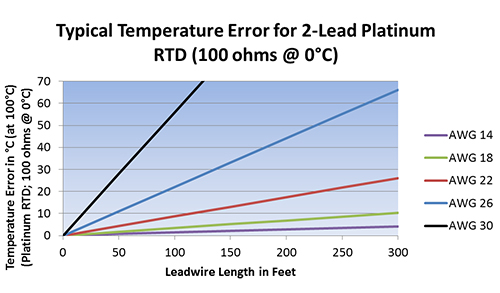
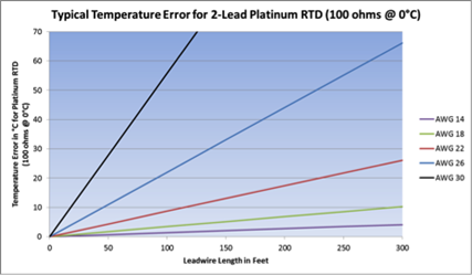
A. 2-lead constructions result in lead-wire resistance getting added to the element resistance. Consequently, the temperature reading is artificially high. The graph below shows the temperature error, from 2 leads of various sizes and lengths, for a 100-ohm platinum RTD at 100°C.
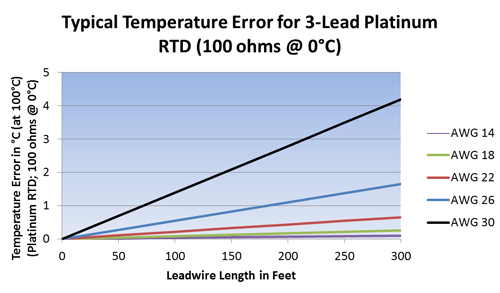
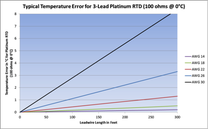
B. 3-lead constructions result in canceled lead-wire resistance error only if the instrumentation can measure true 3-wire resistance.
- Lead-wire resistance error cancellation is most effective when all the lead wires have the same resistance. Using 3 wires of the same AWG, length, and composition will typically result in lead-wire resistances matched within 5%. The graph below shows the temperature error from lead-wire of various sizes and lengths, for a 3-lead 100-ohm platinum RTD at 100°C.
C. 4-lead constructions result in canceled resistance only if the instrumentation can measure true 4-wire resistance. True 4-wire resistance measurement will effectively cancel leadwire resistance error even if all 4 wires are not the same AWG, length, and/or composition.
D. Are any configurations interchangeable?
- 4-lead RTDs can generally be used as 3-lead RTDs by eliminating (or tying off) one of the leads
- 4-lead RTDs can be used as 2-lead RTDs, by combining (shorting) the common leads (usually of like color – white/white and red/red)
WARNING: combining the common leads eliminates lead-wire resistance cancellation benefits - 3-lead RTDs can be used as 2-lead RTDs, by combining (shorting) the common leads ((usually of like color)
WARNING: combining the common leads eliminates lead-wire resistance cancellation benefits
E. See our “Temperature Accuracy Considerations for RTD Measurement Techniques” white paper for detailed analysis.
TCR (Temperature coefficient of Resistance) is the normalized average change in resistance of a sensing element over a specific temperature range (typically 0 to 100°C). The value is independent of the base resistance and is a characteristic of the element material itself. The units are measured in ohms/ohm/°C.
Example: A probe may read 100 ohms at 0°C, but at 100°C, the .00385 probe will read 138.5 ohms and the .00392 probe will read 139.20 ohms.
A. Resistance curve depends on instrumentation. Refer to your instrumentation manual for acceptable RTD (Resistance Temperature Detector) input types.
B. Common TCRs include:
| Material |
Temperature Coefficient |
| Platinum | 0.00385 (EN 60751, IEC 751, DIN 43760, et al) 0.00391 (U.S. industrial standard) 0.00392 (highest purity platinum) |
| Copper | 0.00427 |
| Nickel-Iron | 0.00518 0.00527 |
C. See our Resistance Thermometry white paper for detailed analysis.
There are no firm rules on when to specify transmitters. Each temperature monitoring system has unique cost and accuracy requirements, and unique design problems to overcome.
In general, transmitters offer three advantages:
- Eliminate lead effects from temperature readings
- Output is more immune to electrical noise
- Condition the RTD (Resistance Temperature Detector) signal
A. RTD leads effects: Distance between sensors and control points are an obvious reason to specify transmitters.
Factors to consider:
- Transmitters are more accurate than 2-wire RTDs, if this distance is more than a few feet
- Over large distances, even 3-wire RTD’s can be inadequate for the required accuracy
- 4-wire RTD measurement circuits will effectively eliminate lead wire errors, but the space and cost of two extra leads may exceed the cost of a transmitter
- High resistance sensing elements reduce the effects of lead resistance, but do not eliminate them
- RTD measurement circuits are typically low signal (1 mA or less), and are prone to electrical noise – especially in long wire runs
- At distances over 500 feet, a transmitter may be the only way to carry the accuracy of the RTD to the control electronics
The graph below shows how lead wire resistance introduces temperature measurement error.
B. Electrical Noise: Noise from motors, fluorescent lamps, or other sources will degrade resistance or voltage signals, but has little effect on a transmitter’s controlled current. You may therefore want to use transmitters over relatively short distances in especially noisy areas. The transmitter may even cost less than specially shielded extension wires. Simply twisting the transmitter wire pair is very effective at reducing noise; shielded cable is usually not necessary.
C. Signal Conditioning: You may want transmitters for their signal conditioning circuitry alone. RTD resistance/temperature curves are non-linear. A transmitter changes the RTD resistance to an industry standard 4-20 mA, while simultaneously linearizing the output with temperature. With the transmitter’s linear response, you don’t need complex equations to interpret readings.
Environments containing high voltages or in the presence of electromagnetic fields (EMF) may require shielded lead wires. These environments generate what is commonly referred to as “noise” (EMI) within a sensing instrument. Lead wires act as antennas.
Two common techniques may help alleviate the influence of electrical noise:
- Twisting the leads will help offset the induced noise.
- Lead wires may be covered with a “shielding,” commonly silver plated copper braid (SPC Braid). Grounding the shielding at the instrument only provides the best results.
A thermocouple is called “grounded” when the sensing junction is connected (physically and electrically) to the metal case. There are advantages and disadvantages but generally ungrounded thermocouples are preferable, providing a slower response time is acceptable.
| Thermocouple | Advantages | Disadvantages |
| Grounded | Provides intimate contact for a faster response time | Grounded tip construction is susceptible to induced noise from ground loops, resulting in a less accurate reading |
| Ungrounded | Avoids ground loop issues | Slower response time |
Cold, or reference junction, is the end of a thermocouple that provides a reference point.
Thermocouples measure the difference in temperature between two junctions. They do NOT measure actual temperature. The sensing junction is where the thermocouple wires are welded (or otherwise connected) together, and located at a point where the temperature is desired. The other junction is typically located where it is connected to instrumentation (measuring device). This is known as the cold or reference junction. Thermocouple millivolt tables and mathematical formulas are based on a cold junction temperature of 0°C. To determine actual temperature, the instrumentation must “adjust” for the difference between ambient temperature and 0°C. This adjustment is known as cold junction compensation.
A. Embedment sensors are often potted with an epoxy compound. There are a variety of epoxies or compounds that will support specific applications.
Installers should consider:
- Temperature
- Service conditions
- Chemical compatibility with bearing shoe materials and oils
B. Minco has an array of embedment installation instructions that are available in the resource library of Minco’s website. (EI 164, 167, 180, 181, 184)
To prevent an uncontrolled ground path, electrically isolated probes should be used in insulated bearings, where bearings may be electrically “hot”.
Motors and generators may have insulated bearings to prevent electrostatic discharge and dissipate through a controlled path such as an earth brush. In this condition, a grounded probe may cause damage to the instrumentation as well as damage to the bearings.
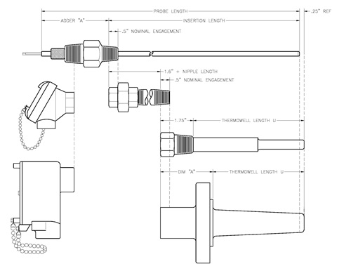
A. Insertion depth is used when an assembly does not utilize a thermowell. Defined as the distance including 50% of the process threads, down to the tip of the probe.
B. Probe length is the complete length of the probe including the length extended inside the connection head. Probe length is calculated by Insertion depth + fitting adder ‘A’.
C. U length is used when an assembly utilizes a thermowell. Defined as the distance from the tip of the thermowell up to the beginning of the process threads.
D. Spring loaded holders offer a little length tolerance flexibility when combining these into an assembly.
E. Get more detailed information in our sensor and instrument product guide.
Based on the design of your system you need to know:
- Operating temperature (°C)
- Operating pressure (bar), Specific volume (m3/kg)
- Velocity (m/s)
Once those are established then you’re ready to consult ASME standard PTC 19.3 TW-2010 Thermowell section, which goes through the calculation for the design of the well.
Here are some basic rules you can follow*:
- In general, higher flow velocity requires shorter thermowells.
- Make sure the thermowell material is compatible with the medium in which it is immersed.
- Economical welded thermowells may be used in low flow applications such as some HVAC chiller lines (typically less than 1-3 ft/sec).
- Tapered thermowells are typically better suited for high flow velocities than step (reduced-tip) thermowells.
*Because Minco’s products are used in a wide variety of applications, the above information is provided for general consideration purposes only. Consult the expert for your specific application or end use prior to implementing any solution. Minco assumes no liability for damages resulting from this information provided.
Minco has an extensive list of products that meet various agency certifications.
Please review the Sensors and Instruments Solution Guide for specific products and certifications associated with each.
Minco has identified a list of the least expensive materials that are compatible with various corrosive media. The unusual temperatures or levels of concentration should also be considered. You can find these in the Material Selection Guide found in the Technical Information sections of the Sensors and Instrument Product Guide.
The list is not comprehensive due to the extensive variety of applications in which Minco products are consumed. Minco encourages customers to perform additional validation for chemicals and materials not specified in the list.
A. Various products are available with optional backing. Installation instruction for these options can be found in:
- Use of Minco Acrylic Pressure-Sensitive Adhesives SPI 00-0603
- Mounting Thermofoil Heaters & Thermal-Ribbon Sensors with #12 Pressure-Sensitive Adhesive SPI 00-0598
B. Alternatively, the following products are available for post-production installation.
Minco offers a variety of thermal-ribbons, probes and accessories suitable for immersion applications.
Consult Sensors and Instruments Solution Guide for specific models suitable for your application