TEMPERATURE SENSORS -
THERMOCOUPLES
THERMOCOUPLES
Minco thermocouples stand out as a superior temperature sensor choice due to their exceptional quality, precision, and reliability across a wide range of applications. Whether in industrial processes, scientific research, or other temperature-sensitive applications, Minco thermocouples have earned a reputation for being the best option, providing unmatched performance and contributing to the overall efficiency of diverse systems. Customers can purchase in-stock thermocouples or partner with Minco to create a custom thermocouple manufactured to their specific needs.
What is a thermocouple
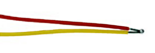
A thermocouple consists of two wires of dissimilar metals welded together into a junction. At the other end of the signal wires, usually as part of the input instrument, is another junction called the reference junction, which is electronically compensated for its ambient temperature. Heating the sensing junction generates a thermoelectric potential (emf) proportional to the temperature difference between the two junctions. This millivolt-level emf, when compensated for the known temperature of the reference junction, indicates the temperature at the sensing tip. Thermocouples are simple and familiar. Designing them into systems, however, is complicated by the need for special extension wires and reference junction compensation.
thermocouple Temperature Sensor Tables in °C and °F
- Type E temperature tables
- Type J temperature tables
- Type K temperature tables
- Type T temperature tables
ADVANTAGES OF A THERMOCOUPLE
Thermocouple advantages include:
- Extremely high temperature capability: Thermocouples with precious metal junctions may be rated as high as 1800°C (3272°F).
- Ruggedness: The inherent simplicity of thermocouples makes them resistant to shock and vibration.
- Small size/fast response: A fine-wire thermocouple junction takes up little space and has low mass, making it suitable for point sensing and fast response. Note, however, that many Minco RTDs have time constants faster than equivalent thermocouples.
HOW DOES A THERMOCOUPLE WORK
- Two Different Metals: Thermocouples consist of two different metal wires or alloys. The point where these two metals are joined is called the junction.
- Seebeck Effect: When there is a temperature gradient along the two different metals, a voltage is generated across the junctions. This voltage is known as the thermoelectric voltage and is a result of the Seebeck effect.
- Direction of Voltage: The direction of the voltage depends on the type of metals used in the thermocouple. In a thermocouple, one wire is designated as the positive leg, and the other is the negative leg. The voltage is measured between these two legs.
- Reference Junction: In practical applications, one of the junctions is kept at a known or reference temperature. This is essential because the thermocouple only measures temperature differences. The reference junction is typically kept at a constant temperature, often using a reference junction compensation (RJC) technique.
- Voltage Measurement: The voltage generated by the thermocouple is proportional to the temperature difference between the measurement junction and the reference junction. This voltage can be measured using a voltmeter or converted into a temperature reading by a temperature-measuring device.
- Linear Relationship: Thermocouples generally exhibit a linear relationship between the temperature difference and the voltage generated. This allows for straightforward calibration and conversion of the voltage signal into a temperature value.
- Thermoelectric Circuit: The combination of the two different metals forms a thermoelectric circuit. The voltage generated is a result of the thermoelectric effect, and this voltage is used as a measure of the temperature at the measurement junction.
- Type of Metals: Different types of thermocouples use different combinations of metals or alloys for the positive and negative legs. Common types include Type K (chromel-alumel), Type J (iron-constantan), and Type T (copper-constantan), each with its own temperature range and characteristics.
- Color Coding: Thermocouples often have color-coded insulation or connectors to indicate the type of thermocouple and facilitate correct connections. The color coding is specific to the metal combination used in the thermocouple.
NEED HELP BUILDING THE RIGHT PART?
Build a part number according to your specifications.
LOOKING FOR A CUSTOMIZED SENSING SOLUTION?
Half of the sensors we produce are custom engineered designs developed for challenging applications. Our Engineers are ready to help.
INTERESTED IN A STANDARD PART?
Fully half our sensors are engineered custom designs that deliver the best fit for challenging applications. Our Engineers are ready to help.